
An attempt to make a 451 bullet mould
Materials: a length of ¾" X 1¾" aluminium bar stock, a length of ½" silver steel, some bits of mild steel, a piece of 1/8" ms plate.
Equipment: a World War 2 military surplus lathe marketed by EH Jones and a WW2 surplus heavy duty pillar drill; two axes vice, Dremel-type tool, Bosch angle grinder, hand tools.

Following some research on the web a cutter was made from the silver steel rod.
It was turned down to form the profile of the bullet based on drawings and dimensions given by a US bullet manufacturer.
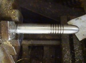
The shaped steel was then marked with two opposite spirals using a felt-tip pen [if I were to repeat the effort, three spirals would probably be drawn].
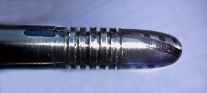
These guides were then used to cut slots using a Dremel cutting wheel, the idea being to make a double edged cutting tool, resembling a tap for threading, with two flutes but with narrow cutting edges.
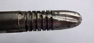

Excess metal to the right of each slot was then carefully ground away using an angle grinder to produce the flutes, leaving the cutting edges proud. The completed cutter was then cleaned-up and heat treated.

The aluminium blocks were made by cutting the stock metal into two lumps. Each had one surface machined flat and should then have had the fine gas grooves cut but this was accidentally omitted until later (an error). The machined surfaces of the blocks were then placed together and the blocks closely aligned, held in a drill vice and four holes drilled. The upper two holes were to locate the temporary guides used when the profile cutter was used to cut the shape of the bullet. The middle two were for the location pegs for the mould.
Location pegs were made and inserted into the holes and the blocks assembled and clamped in a 4-jaw chuck on the lathe and each end faced. The top end had a centre hole lightly cut ready for locating the initial drilling on the pillar drill.
In order to minimise the amount of metal the cutter would have to remove the paired blocks were then placed in the drill vice and drilled firstly with a ¼" drill to virtually the entire length of the bullet then with 27/64" drill.
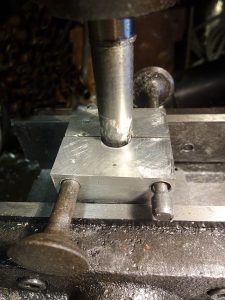
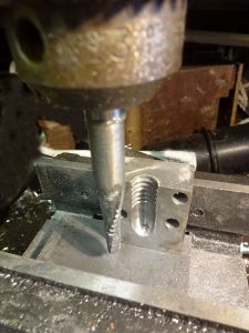
The cutter was inserted in the drill press and carefully lowered ,adjusted and locked in position such that it was the bullet length. One block was placed behind the cutter and the other in front. Two old Mini engine valves (which happened to be a very smooth and precise fit in the holes drilled) were slipped into the upper holes of the blocks to align them. The vice was carefully closed, gently forcing the block faces on to the cutter. Adequate lubrication was applied and the vice loosened so swarf could be removed. The cutter gradually made the bullet shape - but not completely - an oval was formed. This arose because the cutter 'chatted' and initially made a minute ridge on the inner edge of each block. This had to be carefully removed and the cutting restarted. The process was repeated a few times until the blocks were completely closed and the shape fully cut.
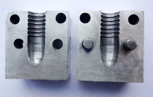
The blocks were removed and the diameter of the bullet shape measured. Further light cutting was repeated until a satisfactory size was obtained. The blocks were then removed again and the faces cleaned and rendered dead flat. At this point is was realised that the gas grooves had not been cut! Cutting them now was a little fiddly - a careless forgetful error - as it meant scoring across the completed bullet hole.
The blocks were then mounted in the lathe and the mould handle slots milled. Then the mould handle securing screw holes were cut and taped.
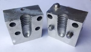
The cut-off plate was cut out and positioned on the blocks then drilled. A hole for the retaining screw first which was aligned with the blocks, one of which was drilled and taped.
The plate then had its filler hole located and drilled. Lyman handles were fitted.
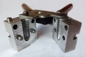
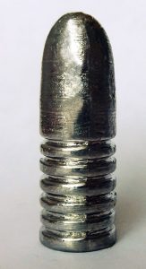
Bullets were cast and measured and the mould blocks returned to the drill press and the cutter applied again with light lateral pressure. This was repeated until the cast bullets were of suitable diameter, slightly over-sized , 0.452". A small Dremel carborundum tool was used, carefully, to finish the interior of the mould.
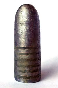
Bullets were sized using a sizer copied from a commercial design (Pedersoli) and dimensions checked; bullets then lubricated ready for testing (!).
In hind-sight I would have made the depth of the lubrication grooves deeper and will in fact alter the cutter to this end and re-cut the mould. It was found that after sizing the grooves were a little shallower than I thought they should be.
To get a better cut, it might be more appropriate to have three or even four cutting edges on the cherry cutter. This would reduce chatter and ensure a better cut.